
Hyundai Elantra: Brake System / Brake Booster Repair procedures
| Brake Booster Operating Test |
| 1. |
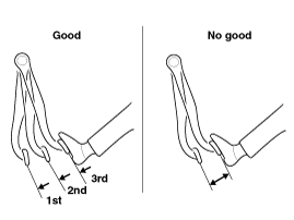
Run the engine for one or two minutes, and then stop it. If
the pedal depresses fully the first time but gradually becomes higher
when depressed succeeding times, the booster is operating properly, if
the pedal height remains unchanged, the booster is inoperative.
|
| 2. |
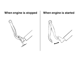
With the engine stopped, step on the brake pedal several times.
Then step on the brake pedal and start the engine. If the
pedal moves downward slightly, the booster is in good condition. If
there is no change, the booster is inoperative.
|
| 3. |
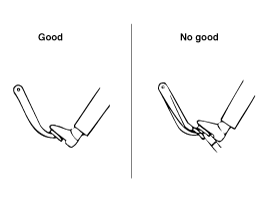
With the engine running, step on the brake pedal and then
stop the engine.Hold the pedal depressed for 30 seconds. If the pedal
height does not change, the booster is in good condition, if the pedal
rises, the booster is inoperative.
If the above three tests are okay, the booster performance can be determined as good.
Even if one of the above three tests is not okay, check the check valve, vacuum hose and booster for malfunction.
|
| Removal |
| 1. |
Turn ignition switch OFF and disconnect the negative (-) battery cable. |
| 2. |
Remove the battery.
(Refer to Engine Electrical System - "Battery") |
| 3. |
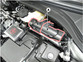
Remove the ECM (A).
|
| 4. |
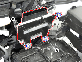
Loosen the mounting bolts (A) and then remova the ECM bracket (B).
|
| 5. |
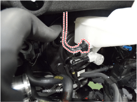
Disconnect the brake fluid level switch connector.
|
| 6. |
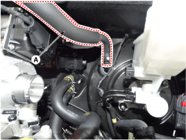
Remove the vacuum hose (A).
|
| 7. |
Remove the brake fluid from the master cylinder reservoir with a syringe.
|

| 8. |
Remove the master cylinder.
(Refer to Brake System -" Master Cylinder") |
| 9. |
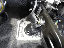
Remove the snap pin (A) and clevis pin (B).
|
| 10. |
Remove the mounting nuts (A).
|
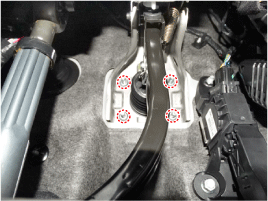
| 11. |
Remove the brake booster. |
| Inspection |
| 1. |
Inspect the vacuum hose. |
| 2. |
Check the boot for damage. |
| Installation |
| 1. |
To install, reverse the removal procedure.
|
| 2. |
After installing, bleed the brake system.
(Refer to Brake System -"Brake System Bleeding")
(Refer to Brake system - "ABS System Bleeding)
(Refer to Brake system - "ESP System Bleeding) |
 Brake Booster Components and Components Location
Components
1. Reservoir cap2. Reservoir3. Booster4. Master cylinder 5. Booster pressure sensor
...
 Vacuum Pump Components and Components Location
Components
[UII 1.6]
1. Camshaft bearing cap2. Camshaft3. Camshaft sprocket4. Vacuum pump5. Vacuum pump gasket
...
Other information:
Hyundai Elantra AD (2016-2020) Service Manual: Head Lamps Repair procedures
Head Lamp Aiming Instructions
[Mechanical Aiming]
The head lamps should be aimed with the proper beam-setting
equipment, and in accordance with the equipment manufacturer's
instructions.
•
If there are any regulations pertinent to the aiming of head
lamps in the ...
Hyundai Elantra AD (2016-2020) Owners Manual: Turn Signal, High Beam, Light ON Indicator Lights
Turn Signal Indicator Light
This indicator light blinks:
When you operate the turn signal indicator.
If any of the following occurs, there may be a malfunction with the turn signal
system.
- The turn signal indicator light illuminates but does not blink
- The turn signal indicator light bli ...
