Hyundai Elantra: Smart Key System / Smart Key Diagnostic Repair procedures
Hyundai Elantra AD (2016-2020) Service Manual / Body Electrical System / Smart Key System / Smart Key Diagnostic Repair procedures
| Inspection |
Self Diagnosis with Scan Tool
It will be able to diagnose defects of SMART KEY system with
GDS quickly. GDS can operates actuator forcefully, input/output value
monitoring and self diagnosis.
The following three features will be major problem in SMART KEY system.
| 1. |
Problem in SMART KEY unit input. |
| 2. |
Problem in SMART KEY unit. |
| 3. |
Problem in SMART KEY unit output. |
So the following three diagnosis operates will be the major problem solution process.
| 1. |
SMART KEY unit Input problem : switch diagnosis |
| 2. |
SMART KEY unit problem : communication diagnosis |
| 3. |
SMART KEY unit Output problem : antenna and switch output diagnosis |
Switch Diagnosis
| 1. |
Connect the cable of GDS to the data link connector in driver side crash pad lower panel, turn the power on GDS. |
| 2. |
Select the vehicle model and then SMART KEY system. |
| 3. |
Select the "SMART KEY Unit". |
| 4. |
After IG ON, select the "Current Data".
|
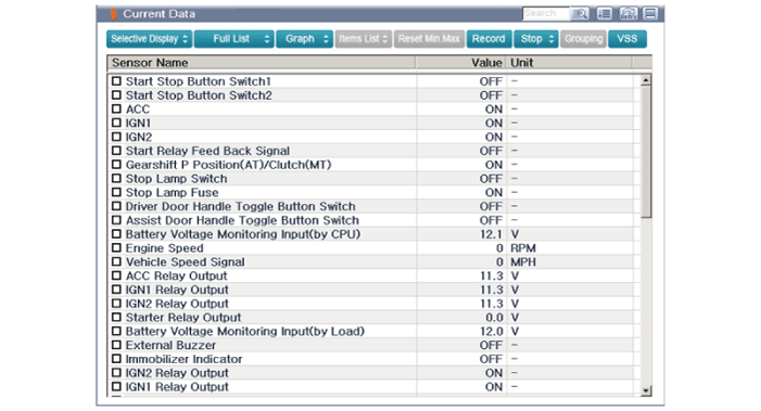
| 5. |
You can see the situation of each switch on scanner after connecting the "current data" process.
|
Communication Diagnosis with GDS (Self Diagnosis)
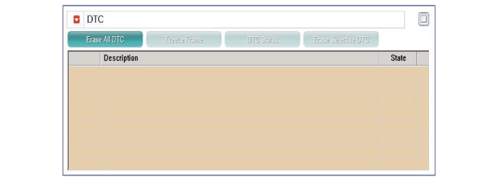
| 1. |
Communication diagnosis checks that the each linked components operates normal. |
| 2. |
Connect the cable of GDS to the data link connector in driver side crash pad lower panel. |
| 3. |
After IG ON, select the "DTC".
|
Antenna Actuation Diagnosis
| 1. |
Connect the cable of GDS to the data link connector in driver side crash pad lower panel. |
| 2. |
After IG ON, select the "Actation Test".
|
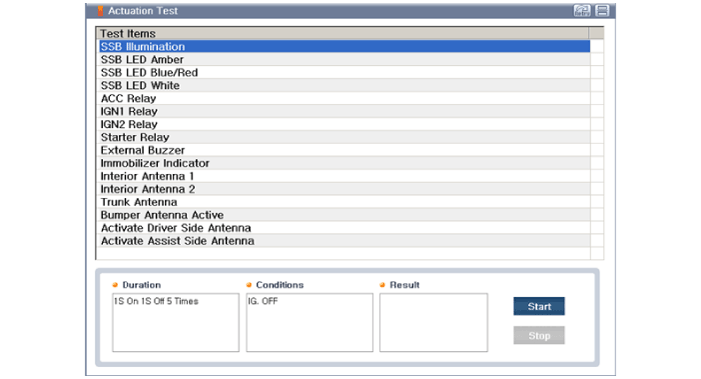
| 3. |
Set the smart key near the related antenna and operate it with a GDS. |
| 4. |
If the LED of smart key is blinking, the smart key is normal. |
| 5. |
If the LED of smart key is not blinking, check the voltage of smart key battery. |
| 6. |
Antenna actuation
|
Antenna Status Check
| 1. |
Connect the cable of GDS to the data link connector in driver side crash pad lower panel. |
| 2. |
Select the "Antenna Status Check".
|
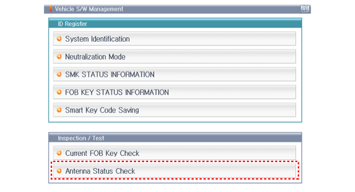
| 3. |
After IG ON, select the "Antenna Status Check".
|
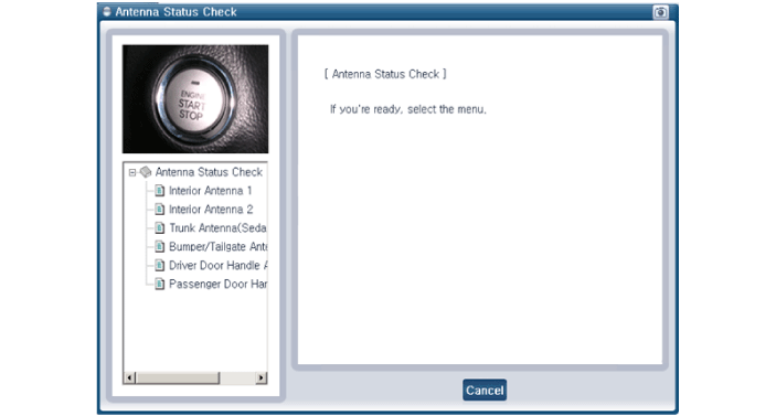
| 4. |
Set the smart key near the related antenna and operate it with a GDS.
|
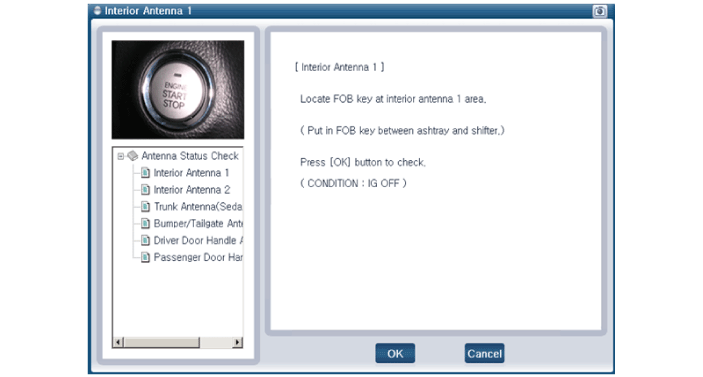
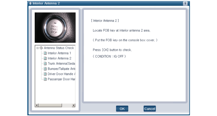
| 5. |
If the smart key runs normal , the related antenna, smart key(transmission, reception) and exterior receiver are normal. |
| 6. |
Antenna status
|
FOB Status Check
| 1. |
Connect the cable of GDS to the data link connector in driver side crash pad lower panel. |
| 2. |
After IG ON, select the "FOB KEY STATUS INFO".
|
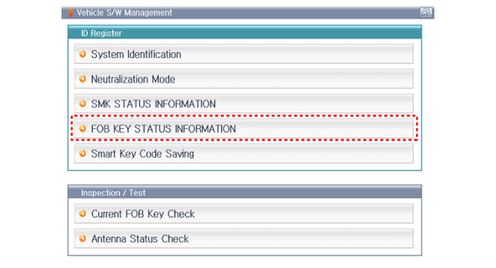

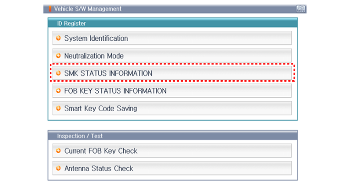
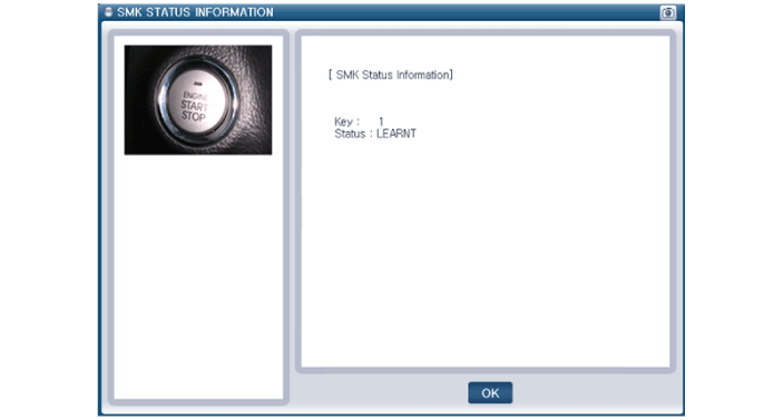
Smart Key Status Check
| 1. |
Connect the cable of GDS to the data link connector in driver side crash pad lower panel. |
| 2. |
After IG ON, select the "SMK STATUS INFO".
|
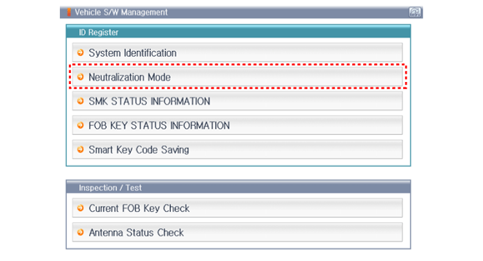
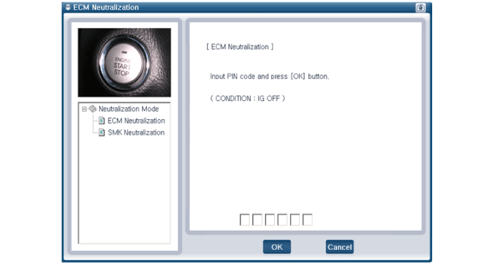
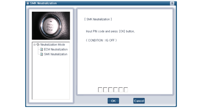
Neutralization Status Check
| 1. |
Connect the cable of GDS to the data link connector in driver side crash pad lower panel. |
| 2. |
After IG ON, select the "Neutralization mode".
|

 Smart Key Unit Repair procedures
Removal
Smart Key Unit
1.
Disconnect the negative (-) battery terminal.
2.
Remove the glove box.
(Refer to Body - "Glove Box Upper Cover Assembly")
3.
Remove the smart key unit (A) after ...

Other information:
Hyundai Elantra AD (2016-2020) Service Manual: Front Disc Brake Components and Components Location
Components
1. Caliper body2. Bleed screw3. Pad return spring4. Brake pad5. Caliper carrier6. Pad inner shim7. Pad retainer
...
Hyundai Elantra AD (2016-2020) Owners Manual: Parking Brake
Checking the Parking Brake
Check the stroke of the parking brake by counting the number of "clicks" heard
while fully applying it from the released position. Also, the parking brake alone
should securely hold the vehicle on a fairly steep grade. If the stroke is more
or less than ...
© 2018-2026 www.helantraad.com
