Hyundai Elantra: Smart Cruise Control System / Smart Cruise Control Unit Repair procedures
Hyundai Elantra AD (2016-2020) Service Manual / Engine Electrical System / Smart Cruise Control System / Smart Cruise Control Unit Repair procedures
| Removal |
| 1. |
Remove the bumper.
(Refer to Body - "Front Bumper") |
| 2. |
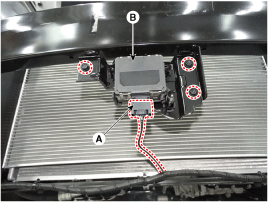
Disconnect the smart cruise control unit connector (A). |
| 3. |
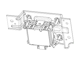
Remove the smart cruise control unit assembly (B) from vehicle after loosening mounting bolts.
|
| Installation |
| 1. |
Install in the reverse order of removal. |
| 2. |
Align the smart cruise control sensor.
(Refer to Engine Electrical System - "Smart Cruise Control(SCC) Alignment") |
| 3. |
Install the bumper cover.
(Refer to Body - "Front Bumper Cover") |
| Smart Cruise Control (SCC) Sensor Alignment |
The objective of the alignment is to ensure correct SCC
performance. In order for the sensor to perform correctly, the sensor
must be aligned correctly. The sensor alignment has major impact on road
estimation, lane prediction, and target processing. When the sensor is
misaligned, the performance of SCC cannot be guaranteed. Therefore, when
the sensor is reinstalled or a new sensor is installed on a vehicle,
the sensor shall be aligned by service personnel.
|

|

Smart Cruise Control (SCC) Radar Alignment
| 1. |
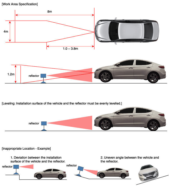
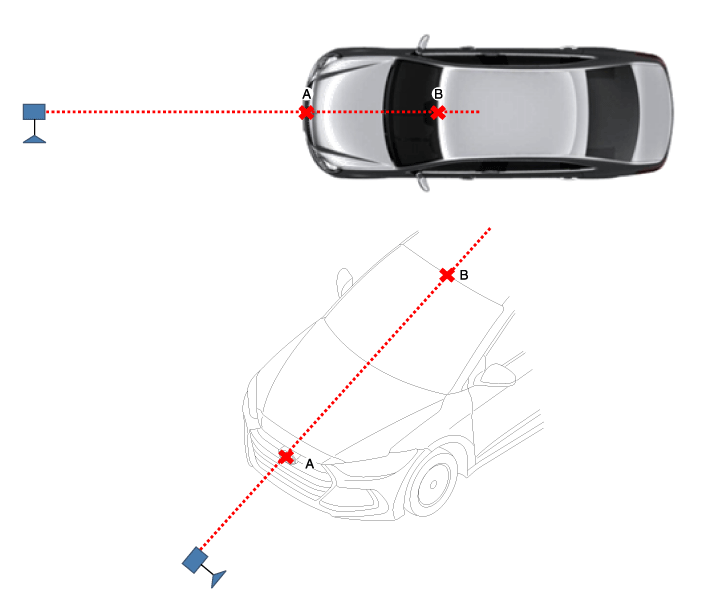
Stop the vehicle horizontally at a flat place.
|
| 2. |
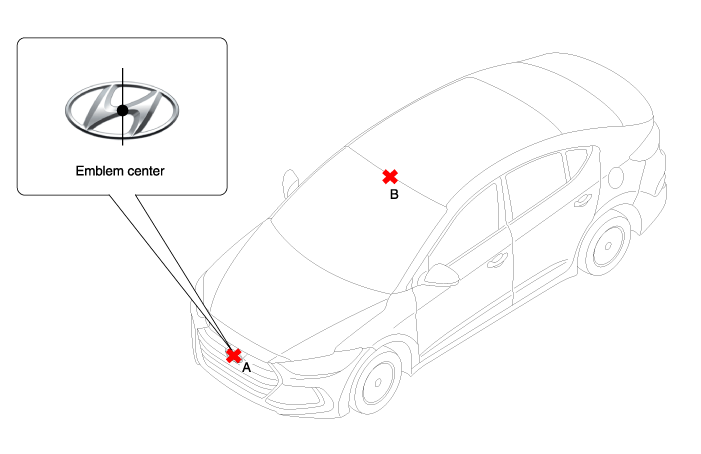
Mark the center point of emblem (A) and the center point on top of wind glass (B).
|
| 3. |
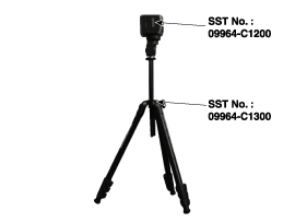
Connect the SCC Calibration Laser (SST No. : 09964-C1200) to the Tri-Pod (SST No. : 09964-C1300).
|
| 4. |
Match the vertical line of laser to (A) and (B) using the SCC calibration laser pointer.
|
| 5. |
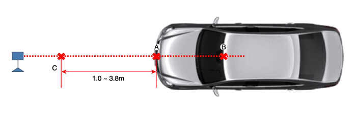
Mark (C) located in 1.0~ 3.8m from (A) in front of the vehicle.
|
| 6. |
Disconnect the SCC Calibration Laser (SST No. : 09964-C1200) from the Tri-Pod (SST No. : 09964-C1300). |
| 7. |
Align the vertical weight of the with the point (C). |
| 8. |
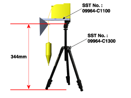
Connect the reflector(SST No. : 09964-C1100) to the tripod(SST No. : 09964-C1300) and set the reflector center height to 344mm.
|
| 9. |
Set the reflector horizontal using the leveler which is built in the tripod(SST No. : 09964-C1300).
|
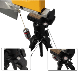
| 10. |
Remove the vertical weight.
|
| 11. |
Check again the radar sensor and the surface of front bumper for the following items with the eyes.
|
| 12. |
Connect the GDS to the DLC of the vehicle and start sensor alignment.
|
| 13. |
After correctly selecting the vehicle model, select "SCC Alignment" from the auxiliary functions in GDS Menu.
|

| 14. |
Perform sensor alignment by following the directions shown in the GDS monitor.
|
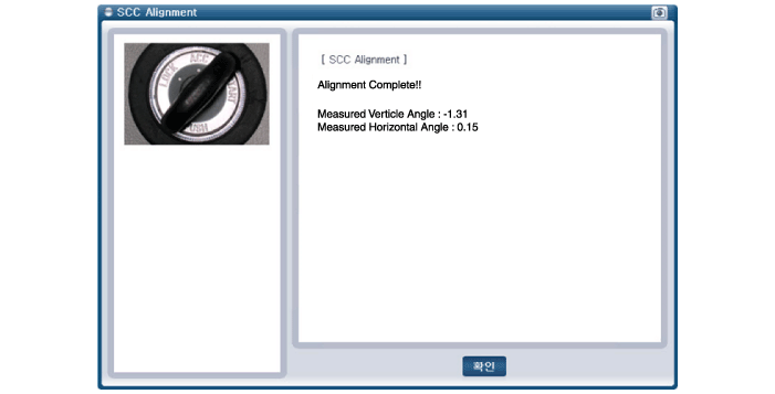
| 15. |
In case of sensor alignment failure, check the alignment
conditions. Turn the ignition key OFF, then reperform the sensor
alignment procedure. |
| Inspection |
Inspection procedures for A smart cruise control system failure
| 1. |
Check the bumper appearance and accidents. (Visual appearance of the vehicle, Maintenance and bumper replacement history)
> If the vehicle has been crashed, SCC mounting part is highly likely to be twisted. |
| 2. |
Check whether the radar sensor cover of the bumper is dirty.
> If the cover is dirty, SCC is highly likely to be released by the foreign substance during operation. |
| 3. |
After engine starting, check SCC warning massage in the cluster and DTC code. (Refer to DTC guide) |
 Smart Cruise Control Unit Schematic Diagrams
Circuit Diagram
...
 Smart Cruise Control Switch Components and Components Location
Components
1. SET - switch2. RES + switch3. SCC switch4. CANCEL switch5. CRUISE switch
...
Other information:
Hyundai Elantra AD (2016-2020) Service Manual: Electric Thermostat (ECT) Description and Operation
Description and Operation
Electric Thermostat (ECT)
Overview
Optimal control of coolant temperature depending on the driving conditions
Operation Principle
Electric Thermostat Structure
...
Hyundai Elantra AD (2016-2020) Service Manual: Antenna Repair procedures
Inspection
Glass Antenna Test
1.
Wrap aluminum foil (A) around the tip of the tester probe (B) as shown.
2.
Touch one tester probe to the glass antenna terminal (A) and
move the other tester probe along the antenna wires to check that
continuity exists.
Glass Antenna Repair
&nb ...
© 2018-2026 www.helantraad.com
