Hyundai Elantra: Driveshaft Assembly / Front Driveshaft Repair procedures
Hyundai Elantra AD (2016-2020) Service Manual / Driveshaft and axle / Driveshaft Assembly / Front Driveshaft Repair procedures
| Removal |
| 1. |
Loosen the wheel nuts slightly.
Raise the vehicle, and make sure it is securely supported. |
| 2. |
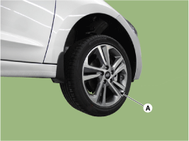
Remove the front wheel and tire (A) from front hub.
|
| 3. |
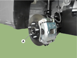
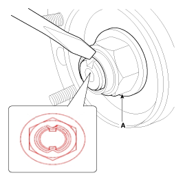
Loosen the driveshaft caulking nut (A).
|
| 4. |
Remove the tie rod end ball joint.
|
| 5. |
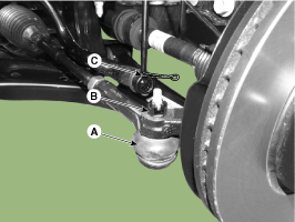
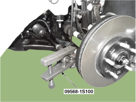
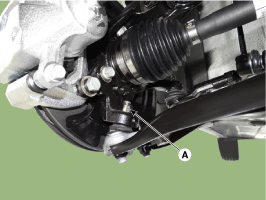
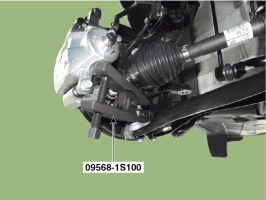
Loosen the lower arm nut (A) and then remove the lower arm ball joint by using SST(09568-1S100).
|
| 6. |
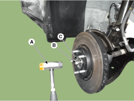
Using a plastic hammer (A), remove the front driveshaft (B) from the knuckle assembly (C).
|
| 7. |
Loosen the inner shaft mounting bolts and then remove the driveshaft. [GAMMA T-GDI RH Only]
|
| 8. |
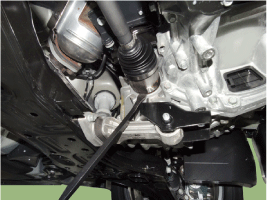
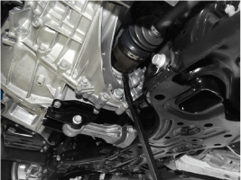
Insert a pry bar between the transaxle case and joint case, and separate the driveshaft from the transaxle case.
[RH]
[LH]
|
| 9. |
To install, reverse the removal procedure. |
| 10. |
Check the front alignment.
(Refer to Suspension System - "Front Alignment") |
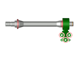
 Front Driveshaft Components and Components Location
Components (1)
[GAMMA T-GDI]
1. Driveshaft (LH)2. Inner shaft bearing bracket3. Driveshaft (RH)
[Except GAMMA T-GDI]
1. Driveshaft (LH)2. Driveshaft (RH)
Components (2)
[RH]
1 ...
 Dynamic Damper Components and Components Location
Components
1. BJ assembly 2. BJ circlip 3. BJ boot band 4. BJ boot 5. Dynamic damper band 6. Dynamic damper7. Shaft8. TJ boot band9. TJ boot10. Spider assembly11. Snap ring12. TJ housing13. Clip
...
Other information:
Hyundai Elantra AD (2016-2020) Service Manual: Inhibitor Switch Description and Operation
Description
•
The inhibitor switch mounted on the upper of transaxle and connected with shifter lever.
•
The inhibitor switch has four points of contact and it makes the signals(S1, S2, S3, S4).
•
The inhibitor switch signals delivered at the TCM according
to control of t ...
Hyundai Elantra AD (2016-2020) Service Manual: Trunk Trim. Repair procedures
Repair procedures
Replacement
•
Put on gloves to prevent hand injuries.
•
When removing with a flat-tip screwdriver or remover, wrap protective tape around the tools to prevent damage to components.
•
When removing the interior ...
© 2018-2026 www.helantraad.com

