
Hyundai Elantra: Body Electrical System / Electro Chromic Inside Rear View Mirror
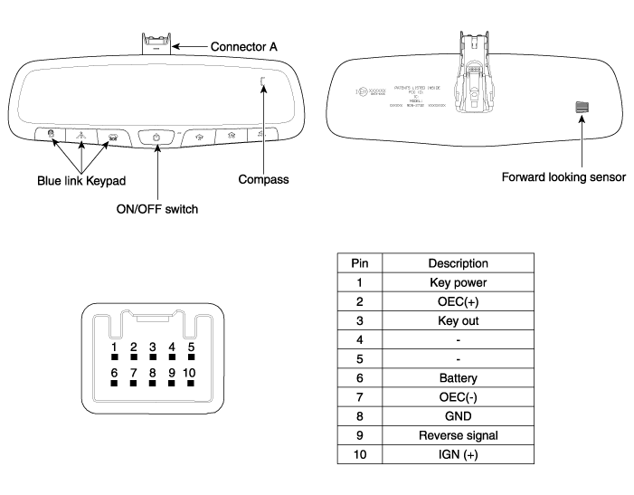
Components and Components Location
| Components (1) |
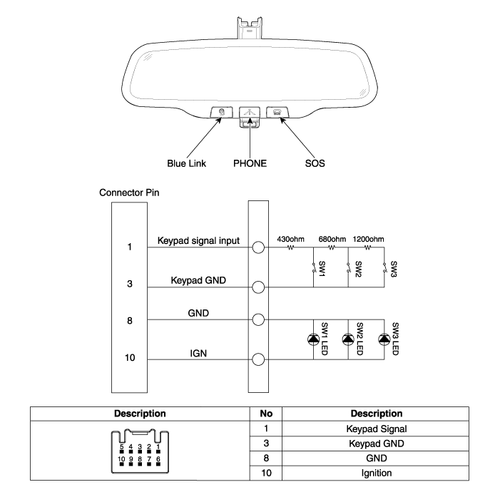
| Components (2) |
Description and Operation
| Description |
| 1. |
The forward facing sensor sees if the brightness of the surroundings is low enough for the mirror to operate its function. |
| 2. |
The rearward looking sensor detects glaring of the reflecting light from a vehicle behind. |
| 3. |
The ECM is darkened to the level as determined by the
rearward looking sensor. When the glaring is no longer detected, the
mirror stops functioning.
|


| Operation |
| Item | Standard Value |
| Rate voltage | DC 12V |
| Operating voltage range | DC9 ~ 16V |
| Operating temperature range | -30 ~ +65°C (-22 ~ 149°F) |
| Direction display | 8 |
| Renewal time | 2 sec. |
| Switch Point | Heading ± 10° |
| N - NE | 22.5 |
| NE - E | 67.5 |
| E - SE | 112.5 |
| SE - S | 157.5 |
| S - SW | 202.5 |
| SW - W | 247.5 |
| W - NW | 292.5 |
| NW - N | 337.5 |
|


| Function |
| 1. |
Press and release the feature control button (A) to turn the display feature OFF. |
| 2. |
Press and release the feature control button (A) again to turn the display back ON.
Additional options can be set with press and hold sequences of the feature control button (A) and are detailed below.
There is a difference between magnetic north and true north.
The compass in the mirror can compensate for this difference when it
knows the magnetic zone in which it is operating. This is set either by
the dealer or by the user. |

Repair procedures
| Inspection |
| 1. |
Turn the ignition key to the "ON" position. |
| 2. |
Cover the forward facing sensor. |
| 3. |
Head a light to the rearward looking sensor. |
| 4. |
The ECM should be darkened as soon as the rearward looking sensor detects the light.
|
| 5. |
When the reverse gear is engaged, the ECM should not be darkened.
When heading lights to both the forward facing and rearward looking sensors, the ECM should not be darkened. |
| Removal |
| 1. |
Remove the mirror wiring cover (A).
|

| 2. |
Remove the mirror connector (A).
|

| 3. |
Remove the mirror (A) pulling up in the arrow direction.
|

| Installation |
| 1. |
Install the mirror making sure the mounting bracket not to be damaged. |
| 2. |
Install the mirror wiring cover and rain sensor cover after reconnecting the connector and tightening the screw. |
 Rain Sensor Repair procedures
Removal
•
The dust or foreign substance on the rain sensor have a bad
effect upon the rain sensor capability,so protect the sensor surface
with protection cover until ...
Other information:
Hyundai Elantra AD (2016-2020) Service Manual: SS-A Solenoid Valve(ON/OFF) Specifications
Specifications
? Control type : Normally low type
ShapeItems Specifications Control current(voltage) [V] 9 ~ 16 Supply pressure [kpa (kgf/cm?, psi)] 490.33 (5.0, 71.12) Control pressure [kpa (kgf/cm?, psi)] 0 ~ 490.33 (0 ~ 5.0, 0 ~ 71.12) Internal resistance(?) 10 ~ ...
Hyundai Elantra AD (2016-2020) Service Manual: Specifications
Specification
ItemResistance (?)Driver Airbag (DAB)1.7 ~ 6.0Passenger Airbag (PAB)1.7 ~ 6.0Knee Airbag (KAB)1.7 ~ 6.0Side Airbag (SAB)1.8 ~ 6.0Curtain Airbag (CAB)1.7 ~ 6.0Seat Belt Pretensioner (BPT)1.7 ~ 6.0Emergency Fastening Device (EFD)1.7 ~ 6.0
Tightening Torques
ItemN.mkgf.mlb-ftP ...
