No
| Ref Symbol
| Name
| Color
| Signal input
| Signal Control
| Check point
|
1
| 
| Turnsignal (Left)
| Green
| CAN
| BCM
(Gateway)
|
|
2
| 
| Turnsignal (Right)
| Green
| CAN
| BCM
(Gateway)
|
|
3
| 
| Tail Lamp
| Green
| CAN
| BCM
(Gateway)
|
|
4
| 
| Fog Lamp
| Green
| CAN
| BCM
(Gateway)
|
|
5
| 
| High Beam
| Blue
| CAN
| BCM
(Gateway)
|
|
6
| 
| Warning
| Yellow
| CAN
| BSD
|
|
TPMS
|
|
SCC
|
|
LDWS
|
|
FCW
|
|
HBA
|
|
BCM
|
|
Hard-wired
| Low Washer
|
| 1. |
Whasher fluid lever sensor |
|
Digital Input
| Reminders when service checks
|
7
| 
| Battery Charge
| Red
| Hard-wired
| Alternator
|
|
8
| 
| Oil Pressure
| Red
| Hard-wired
| ECM
|
|
9
| 
| Check Engine
| Yellow
| CAN
| ECM
|
|
10
| 
| Immobilizer
| Yellow
| CAN
+
Hard-wired
| IMMOBILIZER
SMK
|
|
11
| 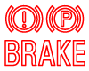
| Parking Brake
Brake Fluid
EBD
EPB
EVP
| Red
| CAN
| BCM
(Gateway)
EBD
EPB
EVP
ABS
TCS
|
| 6. |
Brake Oil Lever Sensor |
|
12
| 
| ABS
| Yellow
| CAN
| ABS
|
|
13
| 
| ESC
| Yellow
| CAN
| TCS
|
|
14
| 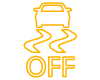
| ESC Off
| Yellow
| CAN
| TCS
|
|
15
| 
| EPB
| Yellow
| CAN
| EPB
|
|
16
| 
| Auto Hold
| White
Yellow
Green
| CAN
| TCS
|
|
17
| 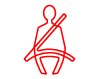
| Seat Belt
| Red
| CAN
| BCM
(Gateway)
|
|
18
| 
| Airbag
| Red
| CAN
| SRSCM
|
|
19
| 
| EPS
(MDPS)
| Red
| CAN
| MDPS
|
|
20
| 
| TPMS
| Yellow
| CAN
| TPMS
|
|
21
| 
| LKAS
| Green
White
Yellow
| CAN
| LKAS
|
|
22
| 
| Fuel Warning
| Yellow
| Direct
(Micom)
| Fuel Sender
|
|
23
| 
| Door Open
| Red
| CAN
| BCM
(Gateway)
|
|
24
| 
| ECO
| Green
| Hard-wired
| ECO Mode
|
|
25
| 
| SPORT
| Yellow
| Hard-wired
| SPORT Mode
|
|
26
| 
| CRUISE
| Green
| CAN
| ECM
|
|
27
| 
| SET
| Green
| CAN
| ECM
|
|
28
| 
| HBA
| Green
| CAN
| LDWS
|
|
29
| 

| AUTO STOP
| Green
Yellow
| CAN
| ECM
|
|
30
| 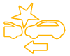
| AEB
| Yellow
| CAN
| SCC
|
|