
Hyundai Elantra: Driveshaft Assembly / Dynamic Damper Repair procedures
| Removal |
| 1. |
Remove the front driveshaft.
(Refer to Driveshaft Assembly - "Front Driveshaft") |
| 2. |
Remove the TJ joint assembly.
(Refer to Driveshaft Assembly - "TJ Joint") |
| 3. |
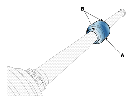
Remove the remove the both side of band (B) of the dynamic damper (A).
|
| 4. |
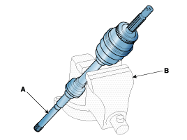
Fix the driveshaft (A) with a vice (B) as illustrated.
|
| 5. |
Apply soap powder on the shaft to prevent being damaged
between the shaft spline and the dynamic damper when the dynamic damper
is removed. |
| 6. |
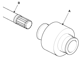
Seperate the dynamic damper (A) from the shaft (B) carefully.
|
| Installation |
| 1. |
Apply soap powder on the shaft to prevent being damaged between the shaft spline and the dynamic damper. |
| 2. |
Install the dynamic damper. |
| 3. |
Install the dynamic damper band. |
| 4. |
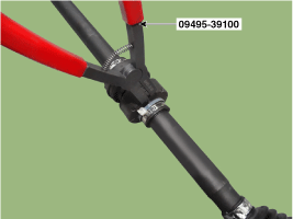
Using the SST(09495-39100), secure the TJ boot bands.
|

| 5. |
Install the TJ joint assembly.
(Refer to Driveshaft Assembly - "TJ joint") |
| 6. |
Install the front driveshaft.
(Refer to Driveshaft Assembly - "Front Driveshaft") |
| 7. |
Check the front alignment.
(Refer to Suspension System - "Front Alignment") |
 Dynamic Damper Components and Components Location
Components
1. BJ assembly 2. BJ circlip 3. BJ boot band 4. BJ boot 5. Dynamic damper band 6. Dynamic damper7. Shaft8. TJ boot band9. TJ boot10. Spider assembly11. Snap ring12. TJ housing13. Clip
...
 TJ Joint Components and Components Location
Components
[RH]
1. BJ assembly 2. BJ circlip 3. BJ boot band 4. BJ boot 5. Dynamic damper band 6. Dynamic damper7. Shaft8. TJ boot band9. TJ boot10. Spider assembly11. Snap ring12. TJ case13. ...
Other information:
Hyundai Elantra AD (2016-2020) Service Manual: Drive Belt Repair procedures
Removal
1.
Remove the drive belt.
(1)
Using the wrench, turning the drive belt tensioner (A) counterclockwise.
(2)
Disconnect the drive belt (A).
(3)
Remove the drive belt tensioner (A) and then remove the drive belt (B).
Inspection
1.
Check belt for maintenance and abnormal wea ...
Hyundai Elantra AD (2016-2020) Service Manual: Power Seat Control Switch Repair procedures
Inspection
Seat Control Switch
1.
With the power seat switch in each position, make sure that
continuity exists between the terminals below. If continuity is not as
specified, replace the power seat switch.
[Power Seat Control Switch]
Removal
1.
Disconnect the negative (-) battery ter ...
