Hyundai Elantra: Engine Control System / Engine Control Module (ECM) Schematic Diagrams
Hyundai Elantra AD (2016-2020) Service Manual / Engine Control/Fuel System / Engine Control System / Engine Control Module (ECM) Schematic Diagrams
| ECM Terminal And Input/Output signal |
| Harness Connector |
| ECM Terminal Function |
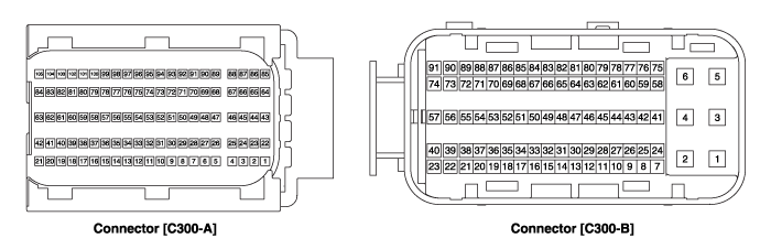
Connector [C300-A]
| Pin No. | Description | Connected to |
| 1 | - | |
| 2 | ETC Motor [+] control output | ETC Motor |
| 3 | - | |
| 4 | Motor [-] control output | Variable Charge Motion Actuator (VCMA) |
| 5 | - | |
| 6 | - | |
| 7 | - | |
| 8 | - | |
| 9 | - | |
| 10 | Clutch switch signal input [M/T] | Clutch switch |
| 11 | - | |
| 12 | - | |
| 13 | - | |
| 14 | - | |
| 15 | Sensor ground | Engine Coolant Temperature Sensor (ECTS) |
| 16 | Engine Coolant Temperature Sensor (ECTS) signal input | Engine Coolant Temperature Sensor (ECTS) |
| 17 | Throttle Position Sensor (TPS) 2 signal input | Throttle Position Sensor (TPS) 2 |
| 18 | - | |
| 19 | - | |
| 20 | - | |
| 21 | Sensor power (+5V) | Manifold Absolute Pressure Sensor (MAPS) |
| Camshaft Position Sensor (CMPS) [Bank 1/Intake] | ||
| 22 | - | |
| 23 | ETC Motor [-] control output | ETC Motor |
| 24 | - | |
| 25 | Motor [+] control output | Variable Charge Motion Actuator (VCMA) |
| 26 | - | |
| 27 | - | |
| 28 | - | |
| 29 | - | |
| 30 | - | |
| 31 | Electrical load signal input | Alternator |
| 32 | - | |
| 33 | - | |
| 34 | - | |
| 35 | - | |
| 36 | - | |
| 37 | Sensor ground | Throttle Position Sensor (TPS) 1,2 |
| 38 | Throttle Position Sensor (TPS) 1 signal input | Throttle Position Sensor (TPS) 1 |
| 39 | - | |
| 40 | Alternator PWM control output | Alternator |
| 41 | - | |
| 42 | Sensor power (+5V) | Throttle Position Sensor (TPS) 1,2 |
| 43 | - | |
| 44 | - | |
| 45 | - | |
| 46 | - | |
| 47 | - | |
| 48 | - | |
| 49 | - | |
| 50 | - | |
| 51 | - | |
| 52 | - | |
| 53 | - | |
| 54 | VCMA Feedback ground | Variable Charge Motion Actuator (VCMA) |
| 55 | - | |
| 56 | Sensor ground | Camshaft Position Sensor (CMPS) [Bank 1/Exhaust] |
| 57 | - | |
| 58 | - | |
| 59 | - | |
| 60 | - | |
| 61 | Sensor ground | Manifold Absolute Pressure Sensor (MAPS) |
| 62 | Manifold Absolute Pressure Sensor (MAPS) signal input | Manifold Absolute Pressure Sensor (MAPS) |
| 63 | Sensor power (+5V) | Camshaft Position Sensor (CMPS) [Bank 1/Exhaust] |
| Variable Charge Motion Actuator (VCMA) | ||
| 65 | - | |
| 66 | - | |
| 67 | - | |
| 68 | - | |
| 69 | - | |
| 70 | - | |
| 71 | - | |
| 72 | - | |
| 73 | - | |
| 74 | Sensor ground | Crankshaft Position Sensor (CKPS) |
| 75 | - | |
| 76 | VCMA Feedback signal input | Variable Charge Motion Actuator (VCMA) |
| 77 | Camshaft Position Sensor (CMPS) [Bank 1/Exhaust] signal input | Camshaft Position Sensor (CMPS) [Bank 1/Exhaust] |
| 78 | Sensor ground | Camshaft Position Sensor (CMPS) [Bank 1/Intake] |
| 79 | - | |
| 80 | - | |
| 81 | - | |
| 82 | - | |
| 83 | VG (Virtual Ground) | Heated Oxygen Sensor [Bank 1/Sensor 1] |
| 84 | VRC (Current Adjust) | Heated Oxygen Sensor [Bank 1/Sensor 1] |
| 85 | - | |
| 86 | - | |
| 87 | - | |
| 88 | - | |
| 89 | - | |
| 90 | - | |
| 91 | - | |
| 92 | - | |
| 93 | - | |
| 94 | - | |
| 95 | Crankshaft Position Sensor (CKPS) signal input | Crankshaft Position Sensor (CKPS) |
| 96 | - | |
| 97 | - | |
| 98 | Camshaft Position Sensor (CMPS) [Bank 1/Intake] signal input | Camshaft Position Sensor (CMPS) [Bank 1/Intake] |
| 99 | Sensor ground | Knock Sensor (KS) |
| 100 | Knock Sensor (KS) signal input | Knock Sensor (KS) |
| 101 | Intake Air Temperature Sensor (IATS) signal input | Intake Air Temperature Sensor (IATS) |
| 102 | - | |
| 103 | - | |
| 104 | VN (NERNST Cell Voltage) | Heated Oxygen Sensor (HO2S) [Bank 1/Sensor 1] |
| 105 | VIP (Current Pump) | Heated Oxygen Sensor [Bank 1/Sensor 1] |
Connector [C300-B]
| Pin No. | Description | Connected to |
| 1 | Power ground | Chassis Ground |
| 2 | Power ground | Chassis Ground |
| 3 | Battery power (B+) | Main Relay |
| 4 | Power ground | Chassis Ground |
| 5 | Battery power (B+) | Main Relay |
| 6 | Battery power (B+) | Main Relay |
| 7 | - | |
| 8 | FLEX-RAY (High) | Other control module, Data Link Connector (DLC) |
| 9 | - | |
| 10 | Accelerator Position Sensor (APS) 2 signal input | Accelerator Position Sensor (APS) 2 |
| 11 | A/C Pressure Transducer (APT) signal input | A/C Pressure Transducer (APT) |
| 12 | - | |
| 13 | - | |
| 14 | Sensor power (+5V) | A/C Pressure Transducer (APT) |
| Fuel Tank Pressure Sensor (FTPS) | ||
| 15 | - | |
| 16 | Sensor power (+5V) | Accelerator Position Sensor (APS) 2 |
| 17 | Sensor power (+5V) | Accelerator Position Sensor (APS) 1 |
| 18 | Main Relay control output | Main Relay |
| 19 | Fuel Pump Relay control output | Fuel Pump Relay |
| 20 | - | |
| 21 | - | |
| 22 | Injector (Cylinder #2) control output | Injector (Cylinder #2) |
| 23 | Injector (Cylinder #3) control output | Injector (Cylinder #3) |
| 24 | - | |
| 25 | FLEX-RAY (Low) | Other control module, Data Link Connector (DLC) |
| 26 | Electrical signal input [Blower Max. Switch] | Heater & A/C Control module |
| 27 | Accelerator Position Sensor (APS) 1 signal input | Accelerator Position Sensor (APS) 1 |
| 28 | Sensor ground | Heated Oxygen Sensor (HO2S) [Bank 1/Sensor 2] |
| 29 | Heated Oxygen Sensor (HO2S) [Bank 1/Sensor 2] signal input | Heated Oxygen Sensor (HO2S) [Bank 1/Sensor 2] |
| 30 | Fuel Tank Pressure Sensor signal input | Fuel Tank Pressure Sensor (FTPS) |
| 31 | - | |
| 32 | - | |
| 33 | - | |
| 34 | Start Motor relay control output | Start Motor relay |
| 35 | CVVT Oil Control (OCV) Valve [Bank 1/Exhaust] control output | CVVT Oil Control Valve (OCV) [Bank 1/Exhaust] |
| 36 | CVVT Oil Control (OCV) Valve [Bank 1/Intake] #1 control output | CVVT Oil Control Valve (OCV) [Bank 1/Intake] #1 |
| 37 | - | |
| 38 | A/C Relay control output | A/C Relay |
| 39 | Injector (Cylinder #4) control output | Injector (Cylinder #3) |
| 40 | Ignition Coil (Cylinder #2) control output | Ignition Coil (Cylinder #2) [NON-Immobilizer type] |
| Ignition Coil (Cylinder #3) control output | Ignition Coil (Cylinder #3) [Immobilizer type] | |
| 41 | Battery power (B+) | Ignition Switch |
| 42 | - | |
| 43 | - | |
| 44 | - | |
| 45 | Sensor ground | Accelerator Position Sensor (APS) 1 |
 Components and Components Location
Components Location
1. Engine Control Module (ECM)2. Manifold Absolute Pressure Sensor (MAPS)3. Intake Air Temperature Sensor (IATS)4. Engine Coolant Temperature Sensor (ECTS)5. Throttle Position ...
 Engine Control Module (ECM) Repair procedures
Removal
•
When replacing the ECM, the vehicle equipped withthe immobilizer must be performed procedure asbelow.
[In the case of installing used ECM]
1) Perform "ECM Neu ...
Other information:
Hyundai Elantra AD (2016-2020) Service Manual: Torque Converter Control Solenoid Valve (T/CON_VFS) Components and Components Location
Components Location
1. 26 Brake Control Solenoid Valve (26/B)2. 35R Clutch Control Solenoid Valve (35R/C)3. Underdrive Brake Control Solenoid Valve (UD/B)4. Overdrive Clutch Control Solenoid Valve (OD/C)5. SS-A Solenoid Valve (ON/OFF)6. Torque Converter Control Solenoid Valve (T/CON)7. Line Pre ...
Hyundai Elantra AD (2016-2020) Service Manual: Center Pillar Trim Components and Components Location
Component Location
1. Center pillar lower trim2. Center pillar upper trim
...
© 2018-2026 www.helantraad.com
