Hyundai Elantra: Engine Control System / Canister Close Valve (CCV) Repair procedures
Hyundai Elantra AD (2016-2020) Service Manual / Engine Control/Fuel System / Engine Control System / Canister Close Valve (CCV) Repair procedures
| Inspection |
| 1. |
Turn the ignition switch OFF. |
| 2. |
Disconnect the CCV connector. |
| 3. |
Measure resistance between the CCV terminal 1 and 2. |
| 4. |
Check that the resistance is within the specification.
|
| 5. |
Disconnect the vapor hose connected with the canister from the CCV. |
| 6. |
Connect a vacuum pump to the nipple. |
| 7. |
Ground the CCV control line and apply battery voltage to the CCV power supply line. |
| 8. |
Apply vacuum and check the valve operation.
|
| Removal |
| 1. |
Turn ignition switch OFF and disconnect the battery negative (-) terminal. |
| 2. |
Remove the canister assembly.
(Refer to Emission Control System - "Canister") |
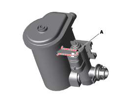
| 3. |
Remove the installation bolt (A), and then remove the air filter (B).
|
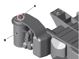
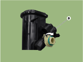
| 4. |
Release the lever (A), and then separate the canister close
valve (B) from the fuel tank air filter after rotating it in the
direction of the arrow in the figure.
|
| 5. |
Install a new fuel tank air filter in accordance with the reverse order.
|
| Installation |
|

| 1. |
Installation is reverse of removal. |
 Canister Close Valve (CCV) Schematic Diagrams
Circuit Diagram
...
 Variable Charge Motion Actuator (VCMA) Description and Operation
Description
The Variable Charge Motion Actuator (VCMA) is installed on the inlet of the intake manifold.
It consists of a DC motor which actuates the VCM valve and a position sensor which detects ...
Other information:
Hyundai Elantra AD (2016-2020) Owners Manual: Driving Your Vehicle
WARNING
Carbon monoxide (CO) gas is toxic. Breathing CO can cause unconsciousness
and death.
Engine exhaust contains carbon monoxide which cannot be seen or smelled.
Do not inhale engine exhaust.
If at any time you smell engine exhaust inside the vehicle, open the windows
immediately. Exposu ...
Hyundai Elantra AD (2016-2020) Owners Manual: System Malfunction
Check Driver Attention Warning (DAW) system
When the warning message appears, the system is not working properly. In this
case, have the vehicle inspected by an authorized HYUNDAI dealer.
WARNING
The Driver Attention Warning system is not a substitute for safe driving
practices, but a c ...
© 2018-2026 www.helantraad.com
