Hyundai Elantra: Automatic Transaxle System / Automatic Transaxle Repair procedures
| 1. |
Remove the engine cover.
(Refer to Engine Mechanical System - "Engine cover") |
| 2. |
Remove the air cleaner assembly and air duct.
(Refer to Engine Mechanical System - "Air cleaner") |
| 3. |
Remove the battery and battery tray.
(Refer to Engine Electrical System - "Battery") |
| 4. |
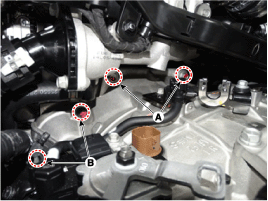
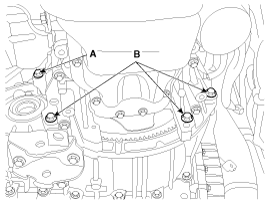
Dissconnect the solenoid valve connector (B) and the inhibitor switch connector (A). 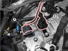
|
| 5. |
Remove fixing clips (A) of the wiring. 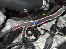
|
| 6. |
Remove fixing clips (A) of the wiring. 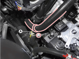
|
| 7. |
Remove the control cable (C) after removing nuts (A) and bolts (B).
Tightening torque:
(B) 14.7 ~ 21.6 N.m (1.5 ~ 2.2 kgf.m, 10.9 ~ 15.9 lb-ft)
(A) 9.8 ~ 13.7 N.m (1.0 ~ 1.4 kgf.m, 7.2 ~ 10.1 lb-ft)
|
|
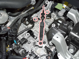
| 8. |
Remove the ground line after removing bolts (A). 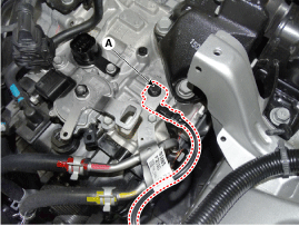
|
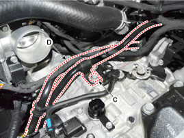
| 9. |
Disconnect the ATF hose (A) from the heater pipe. |
| 10. |
Remove bolts (B) and (C). |
| 11. |
Disconnect the heater pipe (D). 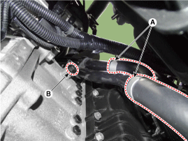
| • |
Carefully install the clamp not to damage the hose. |
| • |
Install the clamp in a correct direction not to be interfered with other parts. |
| • |
After the installation, start the engine and then check if there are any leakages from the hose. |
|
|
| 12. |
Remove the cowl top cover.(Refer to Body-"Cowl top cover") |
| 13. |
Assemble the engine support fixture(beam No.: 09200-38001 or 09200-3N000, supporter No.: 09200-2S000, adapter No.:09200-2W000).
(Refer to Special Service Tools-"Engine support fixture assembly drawing") |
| 14. |
Using the engine support fixture (A), hold the engine and transaxle assembly safely. 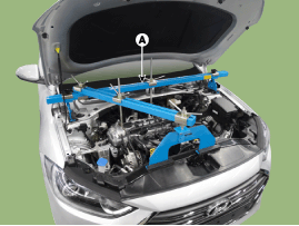
|
| 15. |
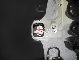
Remove upper mounting bolts(A-2ea) of the automatic transaxle and mounting bolts (B-2ea) of the starter.
Tightening torque:
(A) 42.2 ~ 54.0 N.m (4.3 ~ 5.5 kgf.m, 31.1 ~ 39.8 lb-ft)
(B) 49.0 ~ 63.7 N.m (5.0 ~ 6.5 kgf.m, 36.2 ~ 47.0 lb-ft)
|
|
| 16. |
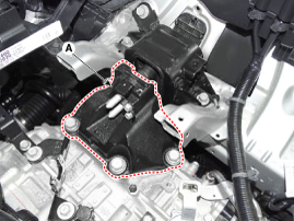
Remove the automatic transaxle mounting bracket cover (A). 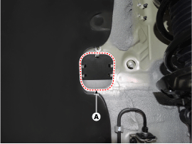
|
| 17. |
Remove mounting bolts (A) of the automatic transaxle support bracket.
Tightening torque:
88.3 ~ 107.9 N.m (9.0 ~ 11.0 kgf.m, 65.1 ~ 79.8 lb-ft)
|
|
| 18. |
Remove the automatic transaxle support bracket (A).
Tightening torque:
58.8 ~ 78.5 N.m (6.0 ~ 8.0 kgf.m, 43.4 ~ 57.9 lb-ft)
|
|
| 19. |
Lift the vehicle with a jack. |
| 20. |
Remove the under cover. (Refer to Engine Mechanical System - "Engine room under cover") |
| 21. |
Remove the drive shaft assembly. (Refer to Driveshaft and Axle - "Front Driveshaft") |
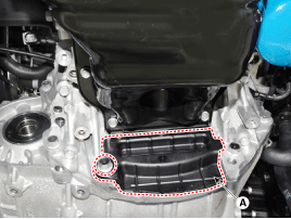
| 22. |
Remove the heater protector (C) after removing bolts (A) and (B).
Tightening torque:
(A) 11.8 ~ 13.7 N.m (1.2 ~ 1.4 kgf.m, 8.7 ~ 10.1 lb-ft)
(B) 21.6 ~ 25.5 N.m (2.2 ~ 2.6 kgf.m, 15.9 ~ 18.8 lb-ft)
|
|
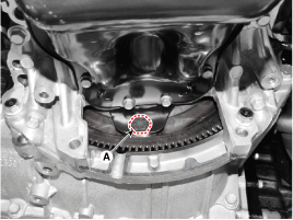
| 23. |
Remove the dust cover (A).
Tightening torque:
42.2 ~ 48.1 N.m (4.3 ~ 4.9 kgf.m, 31.1 ~ 35.4 lb-ft)
|
|
| 24. |
Remove mounting bolts (A) of the torque converter with rotating the crankshaft.
Tightening torque:
45.1 ~ 52.0 N.m (4.6 ~ 5.3 kgf.m, 33.3 ~ 38.3 lb-ft)
|
|
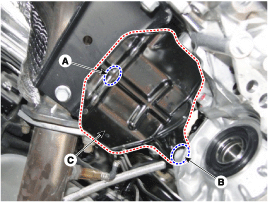
| 25. |
Remove the roll rod bracket (C) after removing bolts (A) and (B).
Tightening torque:
Bolt (B) : 107.9 ~ 127.5 N.m (11.0 ~ 13.0 kgf.m, 79.6 ~ 94.0 lb-ft)
Bolt (A) : 49.0 ~ 68.6 N.m (5.0 ~ 6.0 kgf.m, 36.2 ~ 47.0 lb-ft)
|
|
| 26. |
Remove the roll road support bracket (D).
Tightening torque:
49.0 ~ 63.7 N.m (5.0 ~ 7.0 kgf.m, 36.2 ~ 50.6 lb-ft)
|
|
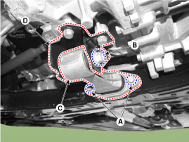
| 27. |
Remove the automatic transaxle with a jack after removing mounting bolts (A, B).
Tightening torque:
(A) 42.2 ~ 53.9 N.m (4.3 ~ 5.5 kgf.m, 31.1 ~ 39.8 lb-ft)
(B) 42.2 ~ 48.1 N.m (4.3 ~ 4.9 kgf.m, 31.1 ~ 35.4 lb-ft)
|
| • |
Be careful not to damage other system or parts near by when removing the transaxle assembly. |
|
|
| 1. |
To install, reverse the removal procedure.
|
Follow the separted each procedure as below according to reinstallation or replacing with a new automatic transaxle. |
|
| 2. |
In case of the reinstallation.
| (1) |
Replace the oil seal with a new one when ATF leak occurred because of differential oil seal damage.
|
When installing the new oil seal, use the special service tool(SST No.:09452-26100, 09231-H1100). |
|
| (2) |
Check the ATF level after refilling the automatic transaxle with fluid. (Refer to Hydraulic System - "Fluid") |
| (3) |
Clear the diagnostic trouble codes (DTC) using the GDS.
|
Even though disconnecting the battery negative terminal, the
DTCs will not be cleared. So, be sure to clear the DTCs using the GDS. |
|
|
| 3. |
In case of the replacing with a new automatic transaxle.
|
New automatic transaxle is already filled with specified quantity ATF.
For that reason, it does not necessary to refill and check
the ATF but the remaining ATF inside of ATF cooler have to be removed. |
| (1) |
Set the air blow gun in front of the ATF cooler hose (A). |
| (2) |
Set the cup in front of the ATF cooler hose (B). |
| (3) |
Remove the remaining ATF by blowing air into ATF cooler hose (A). |
| (4) |
Install the ATF cooler hose (A) and (B). 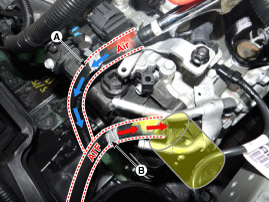
|
| (5) |
Clear the diagnostic trouble codes (DTC) using the GDS.
|
Even though disconnecting the battery negative terminal, the
DTCs will not be cleared. So, be sure to clear the DTCs using the GDS. |
|
| (6) |
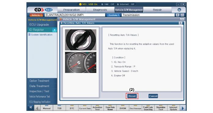
Reset the automatic transaxle adaptive values using the GDS. 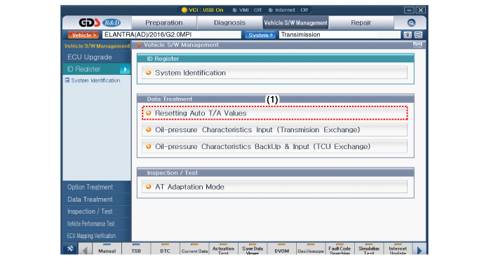
|
| (7) |
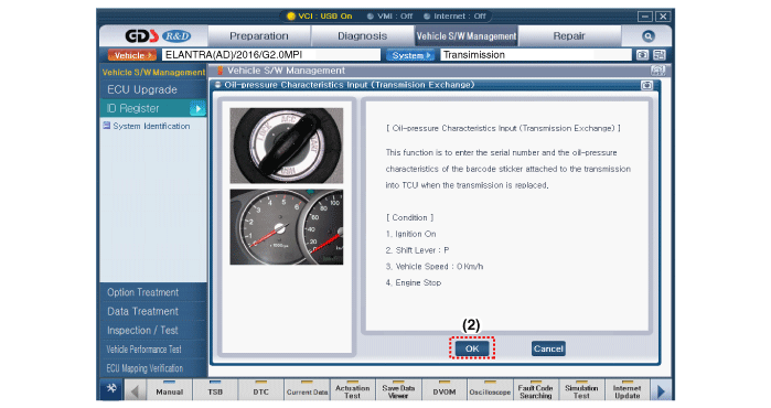
Perform the oil pressure characteristics input procedure.
• Oil pressure characteristics(bar code) location 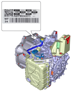
• Oil-pressure characteristics input(Transmision exchange) 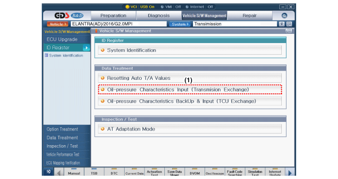

|
| (8) |
Perform the TCM adaptive values learning procedure.
(Refer to Automatic Transaxle Control System - "Repair procedures") |
|
Components Location(1)
1. Automatic transaxle assembly2. ATF cooler tube3. Ground line4. Shift cable mounting bracket5. Shift cable 6. Inhibitor switch & manual control lever7. ATF cooler tub ...
Description and Operation
Description
•
The oil pump is powered by the engine. ATF passes through the oil filter and gets distributed along the oil channels.
•
The oil becomes highly ...


 Automatic Transaxle Components and Components Location
 Hydraulic System