Hyundai Elantra: Charging System / Alternator Schematic Diagrams
Hyundai Elantra AD (2016-2020) Service Manual / Engine Electrical System / Charging System / Alternator Schematic Diagrams
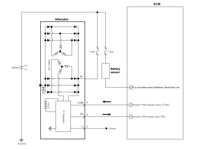
| Circuit Diagram |
|

 Alternator Components and Components Location
Components
1. OAD (Overrunning Alternator Decoupler) 2. Front Bracket3. Front Bearing4. Stator5. Rotor6. Rear Bearing7. Rear Bracket8. Brush Holder Assembly9. Through Bolt10. Rectifier Assembly11 ...
 Alternator Repair procedures
Removal
1.
Turn ignition switch OFF and disconnect the negative (-) battery cable.
2.
Remove the drive belt.
(Refer to Engine Mechanical System - "Drive Belt")
3.
Disconnect the alter ...
Other information:
Hyundai Elantra AD (2016-2020) Service Manual: General Information
General
1.
This measurements are provided as reference for A/S, so it can not be used as specification.
2.
Basically, all measurements in this manual are taken with a tracking gauge.
3.
When a measuring tape is used, check to be sure there is no elongation, twisting or bending.
4.
...
Hyundai Elantra AD (2016-2020) Owners Manual: Head Restraints
The vehicle's front and rear seats have adjustable head restraints. The head
restraints provide comfort for passengers, but more importantly they are designed
to help protect passengers from whiplash and other neck and spinal injuries during
an accident, especially in a rear impact collisi ...
© 2018-2026 www.helantraad.com
